Beiträge von CBM_Ba

    Normal ist doch da keiner, oder? :D


    Ach ja: Falls einer von euch Spielemodule für nen VC20 hat, bitte gaaaanz gerne mitbringen. Ich suche noch ein paar davon. :)


    Dankeschön!


    Entweder bring ich den 8032 mit Plotter, oder den VC20 mit 1020 und Sanyo Röhre mit… ich bin unentschlossen.

    Außerdem den Laptop mit Picomite Basic, damit Franky mir einen Crashkurs geben kann. :P

    Foristen!


    Ich würde gerne den erquicklichen Nachbau der HAL Grafikkarte von zitruskeks mit meinem 2001er testen.


    Leider bekomme ich die Beispielprogramme (Maschinensprache) nicht auf Datasette.

    Mein Setup:

    8032 mit petSD+ und angeschlossener Datasette.

    Ich lade also ganz normal mit DLOAD "PROGRAMM" das Programm und gehe dann mit SYS4 in den Monitor.

    Dort tippe ich S "PROGRAMM",01,0401,2006 ein und speichere das ganze Gedöns auf Datasette.

    Will ich es auf dem PET 2001 laden, so geht das zwar erstmal- ich kann sogar das Programm listen (ok, es ist eben eine Zeilennummer + SYS xxxx). Aber jeder Startversuch wird mit einfrieren des Rechners quittiert.


    Ich vermute, dass meine Start- und Endadressen nicht passen.

    WIE muss ich diese wählen?


    DANKE EUCH! :)

    Vielen herzlichen Dank! :)


    Ja, sieht sehr gut aus- bis auf ein paar Glitches. 255 gibt:


    0 gibt:


    Alles dazwischen gibt schöne Muster. Also werde ich mal deine Nachricht inspizieren und mein Board nachlöten.


    Das Thema Demos und Datasette kuck ich mir mal an. Bin schon wieder unterwegs, zu wenig Zeit für unser Hobby 🤬

    zitruskeks


    Im Schweiße meines Angesichts habe ich nun die Karte + Verkabelung aufgebaut.


    Immerhin: Der Rechner startet noch ganz normal. :D

    Jetzt werfen sich diverse Fragen auf:

    - Woher ist die Software? Bekomme ich sie mit CBMCommand + C64 + Datasette am 64 (funktionsfähig) auf Tape, so dass es der PET versteht?

    - Welche nicht angeschlossene Datenleitung des CharROM hast du auf GND, und welche auf +5V gelegt? Kann man das so einfach mit einem 1:1 Kabel machen, ohne dass der PET Schaden nimmt- oder musstest du ein neues Kabel machen, welches die nicht belegten Leitungen auslässt, um sie anschließen zu können? Oder: Soll ich es bei mir einfach mal ohne Zusatzleitungen testen- so, wie beim Original eben?


    HILFE. DANKE! :)

    Das sieht alles schon ganz gut aus!


    Du hast das RAM/ROM Board im oberen Bild auf 40 Zeichen gejumpert- deshalb war die untere Bildschirmhälfte mit Müll voll.

    Dann hast du umgejumpert (Bild 2) und es passte soweit, aber:

    Die kryptische Tastatureingabe wird daran liegen, dass du ja ein Business-Mainboard mit 80 Zeichen an einer Grafik(Normal)tastatur hängen hast- die sind gänzlich anders beschalten/belegt.

    Diese Kombination kann das RAMROM Board nicht.


    Wann geht denn was? Wenn du nur ROM- oder nur RAM einblendest?

    Falls du den RAM ausschließen kannst, kommt ja nur ein ROM-Defekt in Frage.

    If most of the memory of $ff then the ram is ok … there are some ram locations used for drawing etc but if most turn from 00 to ff then it points to logic …. I guess I am going to have to pull the board and buzz out the tracks against the clone board to figure out what’s not right …. Unless someone has another idea

    Comparing the clone to your original is a really GREAT idea, Andy!

    Would be nice if you could do that. angst :love:

    Have you tried sys59650,1 and tried to change the memory manually ?

    Yes. I'm not able to edit it. Everytime I try, I get the question mark behind the value I tried to change.

    I tried 59650,5 and 59650,1 (switched the PET off between tests)- no chance to change values.


    I also more and more think of a problem with the board... maybe it's one of my TTL logic ICs? But they were all new and freshly ordered for this project from reichelt.de .


    I tried SYS59650,C - you are right, then nearly every value is FF! But the screen looks crazy with all the horizontal lines.


    BR,

    Matthias

    AndyG


    Ok, with your last file I'm able to see some differences:

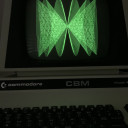
    - Startup (as before) green with black blinking cursor

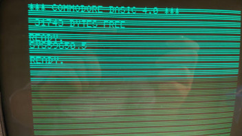
    - Entering SYS 59650,5 now gives me a screen with many horizontal lines (that DIDN'T work with the old version of the HR40-editor ROM I found)

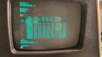
    - I'm now able to see M9000 9040 when entering SYS 59650,5 (there are FF's and sometimes 00's, before there were 9F's everywhere!

    But I can't change values, I always get the question mark behind the changed value when I try that.


    That's all. No more changes at all.

    Here are a few pictures:


    SYS 59650,5 now changes the green screen to something readable:


    And I can see the RAM- here without SYS 59650,5:


    And here after switching the board on with SYS 59650,5:


    Entering POKE35000,4 (so that everything is readable) brings back the 9F... that's why I had to enter it blind after the other things.


    All connections seem to be fine... I think, now there is a point I cannot continue except waiting for the RAM.

    But why is there a green startup screen? :(

    Suggests the latch is not working …. When I get back will send the full edit rom which is basic 2 … you will need to overlay the basic.4 code … I enable my board with the sys59650,5 command.


    You are not getting the vertical bars …. Check the J4/J9 connections ?


    The screen should not be inverted on boot up …

    Ok, is "the latch" an IC on that board? You see I am way too far away from "deeper electronics". ;)

    And why do I have to change from Basic 4 to 2?


    SYS59650,5 is doing nothing at all. When I write a program like this:


    10 FOR A=1 TO 100: SYS 59650,SL,1,1,A,A:NEXT


    I get random flickering, veeery small lines on the screen, which disappear immediately. Looks like the flickering of the old PET 2001 (kind of). :)

    So something IS working? The SYS commands seem to work (for example the "C" command is taking longer time to execute than 59650,5).


    Connections to J4/J9 are double checked and work fine (0 resistance between plug and card).