Prima, daß es direkt jemand gebrauchen kann. ![]()
Könntest Du vielleicht die BIOS-EPROMs auslesen, und zur Verfügung stellen?


Prima, daß es direkt jemand gebrauchen kann. ![]()
Könntest Du vielleicht die BIOS-EPROMs auslesen, und zur Verfügung stellen?
Bin da nicht mehr ganz sicher, meine aber, der Ontrack Disk Manager bietet auch die Möglichkeit an, Partitionierung und Dos-Formatierung mit zu erledigen. Dabei sollte das dann berücksichtigt werden.
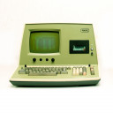
Mir sind zum Octek FOX-II Mainboard Manual und Treiberdiskette zugelaufen.
Das Board hat einen Headland HT-12 Chipsatz, die Diskette enthält dazu den EMS-Treiber.
Anbei ein Scan des Manuals und ein Image der Diskette.
Ein Bild des FOX-II ist hier zu finden: Amoretro
Kaufst halt die Schulden von dem Laden direkt mit. ![]()
Scandisk scannt auf Ebene des DOS-Formats, das ist erst der (über-)nächste Schritt.
Nach dem LL-Format, noch vor der Partitionierung, werden die Bad Sectors eingetragen.
Bei neuen Platten hat man die vom Label abgeschrieben, sofern da welche waren.
Nachdem die Dinger aber schon 30 Jahre auf dem Buckel haben, sind da auch schonmal welche dazugekommen.
Also lässt man die Platte von einem entsprechenden Tool prüfen, das die Bad Sectors dann einträgt.
Mein Tool der Wahl ist - wie schon das eine oder andere mal erwähnt - der Ontrack Disk Manager.
Für die alten Platten passen die Versionen 3.x.
EDIT
Nochwas dazu: Noch vor dem LL-Format ermittelt man den optimalen Interleave.
Der ist nicht nur von Platte und Controller abhängig, wie das LL-Format, sondern auch vom System, in dem das Gespann betrieben wird.
Der optimale Interleave stellt sicher, daß die höchste mit dem System erreichbare Übertragungsrate genutzt wird.
Am schnellsten ist ein Interleave von 1:1. Dafür muß das System in der Lage sein, die Daten einer Spur in einer Umdrehung der Platte entgegenzunehmen.
Die Sektoren stehen dabei auf der Platte entsprechend der Sektornummerierung hintereinander.
Wenn das System es aber nicht schafft, sofort nach dem ersten Sektor den zweiten anzunehmen, muß es warten, bis der wieder unter dem Lesekopf vorbeikommt. Die Platte dreht dann eine Ehrenrunde. Bei einer MFM Platte kann das im ungünstigsten Fall bedeuten, daß die 17 Sektoren einer Spur erst nach 17 Umdrehungen eingelesen wurden. Also werden die Sektoren so auf der Platte abgelegt, daß der nächste zu lesende Sektor dann ansteht, wenn das System eben wieder bereit dafür ist.
Da die Sektoren beim LL-Format auf die Platte geschrieben werden, sollte man also tunlichst vorher den optimalen Interleave ermitteln. Beim LL-Format wird der Interleave abgefragt.

Beide Platten haben selbst nach mehrfachem LLF fehlerhafte Sektoren. Platte Nr. 1 wollte nach dem zweiten LLF sogar die DOS-Installation nicht mehr vollenden (wegen Schreibfehlern von COMMAND.COM / AUTOEXEC.BAT am Ende der Installation).
Hast Du denn die Bad Sectors auch eingetragen?
Das wird beim LLF ja nicht automatisch gemacht, sondern ist ein extra Arbeitsschritt.
Erstmal mit dem Multimeter die Masse-Pins durchklingeln.
Hast Du ein Oszilloskop?
Damit findest Du dann sehr schnell HSync, VSync und die RGB Leitungen.
Die Zuordnung RGB bekommt man leicht raus, wenn man mit den bis dahin bekannten Werten ein Bild hat.
HYsnc und VSync sollte auch mit einem Multimeter mit Frequenzanzeige klappen, wenn kein Oszilloskop da ist.

Mir steht kein Mensch aufgrund der Geografie oder Entfernung näher als ein anderer.
Ich sehe auch keinen Grund "lokale Händler zu unterstützen". Oder den lokalen Handel statt Onlinehandel.
Leute mit solchen Einstellungen sind mehr als unsympathisch.
Normalerweise müsste hier eine Abhandlung über Gesellschaft, Staat, Infrastruktur und was weiß ich noch alles stehen.
Die Vermittlung von diesbezüglichem Grundwissen ist aber nicht mein Aufgabe.
Für mich stellt sich eher die Frage nach Ignorieren oder Rauswerfen.
Boah. Gefährlitsch...
Das Problem dürfte nicht die Temperatur ansich sein, sondern die Temperaturdifferenzen.
Die erzeugen Spannungen im Material.
Also mach das ganze in der Sauna.
Ja, es gibt direkt mehrere Hürden. Erstmal die physikalischen:
- Die mit 100 TPI beschriebenen Disketten können mit einem 96 TPI Laufwerk wegen der unterschiedlichen Spurlage nicht gelesen werden.
- Die 100 TPI Laufwerke aus den CBM Floppys haben keinen Shugart-Bus Anschluß
Und wenn man ein 100 TPI Laufwerk mit Shugart-Bus hätte, bliebe noch offen:
Kommt das Fluxcopy mit den unterschiedlichen Datenraten zurecht?
Je nach Spur werden unterschiedlich viele Sektoren und auch Datenraten verwendet.
Und wie sieht's mit der GCR-Kodierung aus? Oder werden die gelesenen Daten garnicht dekodiert?
Au ha. Hübscher Fehler.![]()
Seit einiger Zeit bin ich davon weg, bei diesen windigen ebay-Händlern aus China zu kaufen.
Geld für defekte oder gefakte Chips haber ich zwar ein paar mal zurückerstattet bekommen, aber der Aufstand für ein paar Euro und dann erneutes wochenlanges warten - da habe ich keine Lust mehr drauf.
Oder bei nie angekommenen Sendungen Hinhaltetaktik bis die Fristen bei ebay/paypal für eine Reklamation abgelaufen sind.
Das ist mir die vordergründig eingesparten paar Euros nicht mehr wert. Bei diesen Mist legt man am Ende doch trotzdem drauf.
Also kaufe ich den Kleinfirlefanz direkt bei einem Händler, der wenigstens in der EU, besser noch in Deutschland sitzt.
Für meine Zeit und meine Nerven kommt das von vorneherein günstiger, für den Geldbeutel am Ende wohl auch.
Eine schöne Anleitung für den richtigen Anschluß der Platten gab es beim alten Ontrack Disk Manager (V 3.x) in der Datei HARDWARE.REF:
. . . . . . . . . . . . . . . . . . . . . . . . . . . . . . . . . . . . . . . .
. .
. Ontrack Computer Systems provides this reference as a .
. service to assist users with their hard disk installation. .
. .
. .................................................. .
. :: PLEASE, :: .
. :: :: .
. :: CONTACT YOUR HARDWARE VENDOR OR MANUFACTURER :: .
. :: :: .
. :: IF YOU HAVE HARDWARE DIFFICULTIES :: .
. ::..............................................:: .
. .
. . For information on DISK MANAGER and specific computers, please .
. check the DM.REF and README files on the DISK MANAGER diskette. .
. .
. . For a printed copy of this, or any other reference file, .
. insert the DISK MANAGER diskette in drive A: and type .
. .
. COPY HARDWARE.REF PRN .
. .
. or replace HARDWARE.REF with the name of the file you want to print. .
. . . . . . . . . . . . . . . . . . . . . . . . . . . . . . . . . . . . . . . .
This file describes the general rules for installing one or two
internally mounted hard disk drives in a PC or AT environment. Any
instructions provided by your dealer will supersede the information
provided here.
The four connections on the disk drive are:
(A) Power (4-conductor), 1 per disk drive.
(B) Command (34-conductor ribbon cable), 1 per 2 disk drives.
(C) Drive select jumper pins, 4 to 8 pair per 1 disk drive.
(D) Data (22-conductor ribbon cable), 1 per disk drive.
Refer to connections (A), (B), (C), (D) in the drawings provided below.
Page 1
__________________________________________________________________
| |
| H H H DDDD D DD |
| H H H D D D |
| H H HHH H HHH H D D DD DDDD D D |
| HHHHH H HH H HHHH D D D D D D |
| H H HHHH H H H H D D D DDD DDD |
| H H H H H H H D D D D D D |
| H H HHH H HHH HHH H DDDD DDD DDDD DD D |
/ /
/ .------------------------------------------------. /
| :NOTE: The connectors shown here may be found in : |
| : different locations on your disk drive. : |
| '------------------------------------------------' |
| |
| |
| |
| AA BBBBBB CCCC DDDDDD |
| AAAA BB BB CC CC DD DD |
| AA AA BB BB CC DD DD |
| AA AA BBBBB CC DD DD |
| AAAAAA BB BB CC DD DD |
| AA AA BB BB CC CC DD DD |
| AA AA BBBBBB CCCC DDDDDD |
| |
| Power Command Cable Drive Select Pins Data Cable |
|__________________________________________________________________|
| 0 0 0 0 | | | | | | | | | | | | | | | | X | | | | | | |
'---------' | | | | | | | | | | | | | | |
|_|_|_|_|_|_| |_| |_|_|_| |_|
* *
* This is the key slot which identifies the side of the connector
towards which the colored edge (pin 1) of the cable must be facing.
AA
AAAA
AA AA
AA AA
AAAAAA
AA AA
AA AA
The power cable is keyed to ensure proper orientation. A separate power
cable must be connected to each hard disk drive. There is no distinction
between the power cables for drive 1 or drive 2.
BBBBBB
BB BB
BB BB
BBBB
BB BB
BB BB
BBBBBB
There are several types of command cables used to connect the hard disk
to the controller. You will need to determine which of the cables listed
below matches the cable you are using. The type of cable you are using will
determine where the drive select jumper should be on your hard disk.
Page 2
The pin nearest to the notch on the edge connector is pin 1. Pin 1 on
the command cable may be identified by any of the following:
1. A triangle stamped on the connector, OR
2. A colored stripe on the end conductor of the cable, OR
3. A keying tab inside the connector (to prevent reverse insertion.)
This cable is used in a system that has only one hard disk.
.-------------------.
| Connected to the |
| controller |
|___________________|
* | | | | | | | |
.---------->* | | | | | | | |<-----------------------------.
|The star * | | | | | | | | This cable is designed for |
|line * | | | | | | | | use with a single hard disk. |
|indicates * | | | | | | | | The drive select jumper must |
|the * | | | | | | | | be on the first position and |
|colored * | | | | | | | | the terminating resistor |
|edge of * | | | | | | | | should be left on the drive. |
|the cable * | | | | | | | |<-----------------------------'
---------->* | | | | | | | |
.-------------------.
| Connected to a |
| single hard disk. |
'-------------------'
The cable shown below is designed for use in systems that have two hard
disks, although it can also be used in single hard disk systems. When
attaching the cables to your hard disk and floppy disk drives, please make
note of the following:
1. The cable used on the floppy drive has the reversed (twisted) wires
nearest the edge with the colored wire (pin 1), AND
2. The wide (command) cable attached to the hard disk has the twisted (*)
wires furthest from the edge with the colored wire (pin 1).
* Your hard disk command cable may not have any twisted wires. If this is
the case, please see the note below.
Page 3
.------------------.
| Connected to the |
| controller |
'------------------'
* | | | | | | | |
.----------->* | | | | | | | |
|The star * | | | | | | | |
|line * | | | | | | | |
|indicates * | | | | | | | |
|the * | | | | | | | |
|colored * | | | | | | | |
|edge of * | | | | | | | |
|the cable * | | | | | | | |
----------->* | | | | | | | | .--------------------------------.
* | | | | | | | | | This connector is for the 2nd |
* | | | | | | | | | hard disk in the computer. The |
* | | | | | | | | | drive select jumper should be |
* | | | | | | | | | in the 2nd position and the |
.-------------------. | terminating resistor should be |
| Connected to the | <-' removed from the disk drive. |
| 2nd hard disk. | <----------------------------------'
'-------------------'
* | | | | | | | | .----------------------------.
* | | | | |\ /| | |If your cable does NOT have |
* | | | | | | | |this twisted set of wires, |
* | | | | | T | | |then drive one must have the|
* | | | | | W | |<-----'drive select jumper in the |
* | | | | | I | | NOTE! 1st position. |
* | | | | | S | |<-----. * CAUTION * |
* | | | | | T | | |THIS APPLIES ONLY WHEN THERE|
* | | | | | | | |IS NO TWIST IN THE CABLE!! |
* | | | | |/ \| | '----------------------------'
* | | | | | | | |
.------------------.
|Connected to the | <--------------------------------.
|1st hard disk | <. This connector is for the 1st |
'------------------' | hard disk in the computer. If |
| your cable DOES have a twist, |
| then the drive select jumper |
| should be in the 2nd position |
| and the terminating resistor |
| should be left on the disk |
| drive. |
'-------------------------------'
CONTROLLERS:
The controller pictured here is typical of PC/XT type controllers. Your
hard disk controller may have a different layout of components, but it
should have the connectors shown in the diagram.
To properly connect the command and data cables to the hard disk
controller, pin 1 must be located on the cable as well as on the
controller. Pin 1 on the controller may be located by one of the
following methods:
Page 4
1. The number 1 printed on the card near one end of the row of pins (as
shown in the diagram), OR
2. A square solder mark on the back side of the controller where the row of
pins are soldered to the controller, OR
3. Controller card documentation.
Pin 1 on the cables may be located by one of the following methods:
1. A triangle stamped on the connector, OR
2. A colored edge on one side of the ribbon cable, OR
3. A keying tab may be inside one of the connector holes that mates with a
missing pin on the controller.
| Command cable |
|_______________|
Data cable for _______________________________|_____________________ .----
the 1st drive | | ____ | |
-------------------|---> :::::::::: ::::::::::::::::: |____| | |
| 1 1 | |
-------------------|---> :::::::::: _______ _______ ____ | |
Data cable for | 1 | | | | |____| | |
the 2nd drive | ____ | | | | | |
| |____| |_______| |_______| ____ | |
| _______________ |____| | |
| | | ____ | |
| | | ____ ____ |____| | |
| |_______________| |____||____| ____ | |
| |____| | |
| 8 Bit Hard Drive Controller | |
|____________________________________________________| |
| | | | | | | | | | | | | | | | |
|_|_|_|_|_|_|_|_|_|_|_|_|_|_|_| |
The controller pictured below is typical of PC/AT type controllers. Your
hard disk controller may have a different layout of components, but it
should have the connectors shown in the diagram. To properly connect the
command and data cables to the hard disk controller, pin 1 must be located
on the cable as well as on the controller. Pin 1 on the controller may be
located by one of the following methods:
1. The number 1 printed on the card near one end of the row of pins (as
shown in the diagram), OR
2. A square solder mark on the back side of the controller where the row of
pins are soldered to the controller, OR
3. Controller card documentation.
Page 5
Pin 1 on the cables may be located by one of the following methods:
1. A triangle stamped on the connector, OR
2. A colored edge on one side of the ribbon cable, OR
3. A keying tab may be inside one of the connector holes that mates with a
missing pin on the controller
_______________________________
| |
| __ |
| _ ____ |__ |
| _ | | | | |__ |
| | | |_| | | |__ |
| |_| | | |
| |____| |
| |
| |
| ____________ _____ |
| | | | | |
| |____________| | | |
| _ _ | | |
| | | | | | | |
| |_| |_| |_____| |
| | Data cable (D) for disk 2
| _ _ J3 ::::::::: |<---------------------------------
_____| | | | | |
|_____| |_| |_| | Data cable (D) for disk 1
|_____| __ J2 ::::::::: |<---------------------------------
|_____| | | |
|_____| | | | Command cable (B) for disk 1 & 2
| | | J1 :::::::::::::::: |<---------------------------------
_____| | | |
|_____| |__| | This cable header is for floppies.
|_____| _ J4 :::::::::::::::: |<---------------------------------
|_____| | | |
|_____| |_| |
|_____| _ _ _ |
|_____| | | | | | | |
|_____| |_| |_| |_| |
|_____| _ _ _ _ |
|_____| | | | | | | | | |
| |_| |_| |_| |_| |
|_______________________________|
____________________________________
|
|
|
CCCC
CC CC
CC
CC
CC
CC CC
CCCC
Page 6
The drive select jumper on your hard disk needs to be set according to
the command cable used in your system. The proper drive select may be
determined as follows:
1. If you are using a command cable with a single hard disk connector, the
drive select jumper should be in the 1st position.
2. If you are using a command cable with connectors for two hard disks and
wires 25-29 are reversed (twisted) between the two hard drive
connectors, then BOTH HARD DISKS (*) should have the drive select jumper
in the 2nd position.
3. If you are using a command cable with connectors for two hard disks and
none of the wires are reversed (twisted), then the drive select jumper
should be in the 1st position for drive one and the 2nd position for
drive two.
* The reversed wires make a hard disk with the drive select jumper in the
second position react as drive one.
DDDDDD
DD DD
DD DD
DD DD
DD DD
DD DD
DDDDDD
The data cable is the narrow ribbon cable. You will need one data cable
for each hard disk installed in the computer.
. . . . . . . . . . . . . . . . . . . . . . . . . . . . . . . . . . . . . . . .
. .
. Ontrack Computer Systems provides this reference as a .
. service to assist users with their hard disk installation. .
. .
. .................................................. .
. :: PLEASE, :: .
. :: :: .
. :: CONTACT YOUR HARDWARE VENDOR OR MANUFACTURER :: .
. :: IF YOU HAVE HARDWARE DIFFICULTIES :: .
. ::..............................................:: .
. .
. . For information on DISK MANAGER and specific computers, please .
. check the DM.REF and README files on the DISK MANAGER diskette. .
. .
. . For a printed copy of this, or any other reference file, .
. insert the DISK MANAGER diskette in drive A: and type .
. .
. COPY HARDWARE.REF PRN .
. .
. or replace HARDWARE.REF with the name of the file you want to print. .
. .
. . . . . . . . . . . . . . . Page 7 . . . . . . . . . . . . . . . . . . . . .Bei zwei Platten entweder gedrehtes Kabel und beide Platten auf DS1, oder gerades Kabel und DS1 und DS2.
Und natürlich immer nur an der Platte am Kabelende die Terminatoren stecken.
Dieser Kwark mit den gedrehten Kabeln nervt mich ja schon bei den Floppys, da kommt man aber beim PC dank der Belegung des Ports nicht drumrum. Bei den Platten geht's zum Glück ohne.
Komisch...
Vielleicht weiß for(;;) was da los ist?
Einfach mit FAT32 formatieren, das wars schon.

Für ein analoges Oszi spricht imho nichts mehr heutzutage aus praktischen Erwägungen als "Arbeitsgerät".
Da ich nach wie vor nur mit meinem analogen 100 MHz Tektronix arbeite kann ich da nur eingeschränkt mitreden.
Aber:
Mir ist es zB nicht gelungen, bei der Justage eines Diskettenlaufwerks mittels analoger Alignmentdisk, die CAT-Eyes dar zu stellen. Das kann nur analog !
Sollte mit dem digitalen das Justieren eines Diskettenlaufwerks tatsächlich nicht klappen, wäre es eigentlich unverzichtbar.
Bei denen unter'm Strich fehlt dann aber jeweils die 'Vorsilbe' 74/54... nehme ich an?
Ansonsten wüsste ich jetzt nicht viel damit anzufangen.
Auf welchem Kopf werden die Fehler denn gemeldet?
Wenn es der letzte ist, kann man z.B. die Anzahl der Köpfe um 1 reduzieren.
Wenn das nicht passt: Da die Platte eh hinüber ist, kann man auch einen gewagten Rettungsversuch unternehmen.
Ob das überhaupt möglich ist, hängt vom mechanischen Aufbau der Platte ab.
Bei manchen Platten kann man die Spur 0 verschieben, entweder indem man den Spur 0 Sensor verstellt, oder die Kopfmechanik verstellt.
Wenn man die Spur 0 dadurch auf einen fehlerfreien Bereich verschieben kann, verliert man zwar am Ende einige Spuren, kann die verbleibenden aber noch nutzen.
Beide Methoden bringen aber nur dann was, wenn die Platte nicht sowieso in vollständiger Auflösung durch immer mehr hinzukommende defekte Sektoren ist.
Eine von den beiden Platten ist defekt, habe ich trotzdem als eventuellen Teilespender mit eingepackt.
Daß die Werte der einzelnen Type im BIOS-Setup angezeigt werden ist der Normalfall.
Wenn das bei Dir nicht so ist, wäre das durchaus eine Erwähnung Wert.
Und dann natürlich noch weitere Informationen, mit der man vielleicht irgendwo die Tabelle der hinterlegten Plattenparameter finden kann.
Oder, auf den Punkt gebracht: Damit man Dir hier helfen kann, ist Deine Mitarbeit unerläßlich.
Ach ja: Ist da ein 8 Bit oder ein 16 Bit MFM Controller drauf?

ps. wie würde ich denn eine andere HDD, zB Quantum 52AT, an einen entsprechenden Controller gehängt, im BIOS eintragen, wenn dort "47" user type" nicht zur Verfügung steht, sondern nur die (vordefinierten) Ziffern 1...46?
Einen vordefinierten Plattentyp auswählen, bei dem die Anzahl der Köpfe und Spuren vorzugsweise gleich, auf keinen Fall aber größer als bei der angeschlossenen Platte ist, und die Differenz in der Kapazität möglichst gering ist.
Ich würde mal ein 5,25" 360KB Laufwerk probieren.
Vielleicht initialisiert das BIOS den FDC nicht auf die richtige Datenrate.
Insbesondere auf Taiwan 286er Boards findet sich manchmal ein mit heißer Nadel zusammengeschustertes BIOS.
Wird denn beim Boot auf das Floppylaufwerk zugegriffen?
Was für ein Laufwerk ist das?

Schau an... Grand Prix Circuit läuft bei mir auch nicht.
Hast Du auch die EGA-Version getestet?
Ich wollte nochmal die CGA-Version ausprobieren.
Ich hab nur eine Version, bei der man am Start auswählen muss (3 für EGA). Wähle ich die 1 für CGA, passiert nix.
Es sei denn, es gibt noch eine andere Version davon?
Je nach ausgewählter Grafikkarte wird eine andere .EXE gestartet.
Also GPCGA.EXE, GPEGA.EXE GPTDY.EXE.
Schau an... Grand Prix Circuit läuft bei mir auch nicht.
Hast Du auch die EGA-Version getestet?
Ich wollte nochmal die CGA-Version ausprobieren.
Da fällt mir ein, daß VGA-Copy/386 auch auf einem 286er läuft. Habe ich die Tage mal ausprobiert. ![]()
Endlich habe ich einen Aristo-Taschenrechner M 76 von ca. 1977 bekommen.
Rechner lasse ich ja gelten, aber Taschenrechner? Na, ich weiß nicht...
Auf jeden Fall ein echter Hingucker.
War da bei den Conner-Platten nicht mal was mit einem klebrig gewordenem Puffer, an dem der Arm mit den Köpfen hängenbleibt?
MarNo84 hatte da mal eine Reparaturmöglichkeit dokumentiert, glaube ich.