
Ritto wäre der passende Hersteller in dem Bereich...
Bei der gegebenen Antwort fehlt der zwei Posts vorher genutzte
<klugscheissmodus>
![]()
![]()


Ritto wäre der passende Hersteller in dem Bereich...
Bei der gegebenen Antwort fehlt der zwei Posts vorher genutzte
<klugscheissmodus>
![]()
![]()
I have found the schematics for the Motorola MD1000, adjusted some resistor values to accommodate the Samsung CRT. It works nicely in place of the NEC.

I have found the schematics for the Motorola MD1000, adjusted some resistor values to accommodate the Samsung CRT. It works nicely in place of the NEC.
Good to see…
xesrjb
Can you document the changes for people facing the same problem? Even though obvious its for one specific type of replacement CRT.
I can imagine its especially for the deflection as the deflection angles of the tubes differ?
I think the only documentation you would ever need is the schematics. I am happy to share that. I'm also around and happy to help.
@nilseuropa: Very nice Osborne with a shiny new Tube! ![]()
I was lucky enough to get such a little CRT module with an amber tube.
The module takes composite video as well as VGA signal up to 800x600!
@nilseuropa: Very nice Osborne with a shiny new Tube!
I was lucky enough to get such a little CRT module with an amber tube.
The module takes composite video as well as VGA signal up to 800x600!
ooh, that is exciting. what are your plans with it? ![]()
Hi nilseuropa,
please tell us the source of your CRT Schematic.
May be it is usefull for outhers.
Best regards Klaus Loy
ooh, that is exciting. what are your plans with it?
This is going to be a DIY-8bit-Computer, the so called "Kramer-MC" (Kramer-Microcomputer).
The plans to build this Z80-Computer have been published in the late 1980s in the GDR by Manfred Kramer.
During the first Corona-Lockdown in 2020 i found the time to build my own prototype.
The process is documented in the "robotrontechnik-forum":
Der Buchführungs-PC einer Kundin (i7-6700, 32GB, 1TB SSD, GTX980) wurde so langsam zum Dauerkandidaten zur Reparatur. Dass sie die Leistung nicht nutzen könnte und es wäre, als ob sie mit einem Sportwagen durch die 30er Zone fahren würde und alternativ auch ein Fahrrad nutzen könnte hat sie nicht überzeugt.
Jetzt hat sie einen I5-6600, 16GB, 512GB, Onboard-Grafik ("Ich dachte für ein gutes Bild muss es eine gute Grafikkarte sein.", "Ja 1995"), zu weniger konnte ich sie nicht überreden. Ich habe von ihr nix mehr gehört, was ich wohl als gutes Zeichen betrachten kann. Wird mit der M.2-SSD wohl schneller sein, als der Alte.
Jetzt habe ich hier ihren Defekt PC, jedes Teil nochmal geprüft und hatte folgendes Problem: Mainboard startete nur mit entfernter BIOS-Batterie, ansonsten nur Diagnostik LED neben dem ATX-Stecker. Um das als Defekt verkaufen zu können, muss ich den Fehler ja eingrenzen.
Scheint beim Z170A Krait Gaming ein Standart-Problem zu sein aber die Lösung heißt immer: BIOS-Batterie raus, dann läuft es bis zum nächsten Mal.
Ich hab nun das neues BIOS drauf und aktuell scheint es wieder zu laufen.
Kann jemand ähnliches Berichten oder hat eine Idee?
Guten Abend
Evt liegt es am DMI Interface anhand der Info, wenn der Rechner ohne BIOS Batterie hochläuft,
Vorschlag :
überprüfe die Bios Einstellungen, ggf deaktiviere mal die Optionen, Mainboard Spezifische Bereiche,
Buchführung und GTX980 ![]()
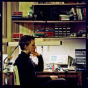
Ich bastle gerade am 8296 von Holger, dazu erklingen wohlige Weihnachtsklänge vom SID, sowie erquickliche Grafiken von der Commodore Weihnachtsdemo auf dem Tannenbaummodul. ![]()
Besser als jede Therapie, Foristen!
![]()
ist das ein brother etiketten drucker?
lg
helmut

Meinst Du das Ding links oberhalb vom C64 in dem Bild von CBM_Ba ... wenn ja dann ist das eine Weller Lötstation.
oje, ich werde alt, ich dachte da steht ein drucker auf der unteren lötstation ![]()
Ich habe heute endlich den Gotek als Emulator für das (defekte) HP-9130A am HP-86 fertiggestellt. Das Pinout des Centronics-Floppy-Steckers am HP-86 habe ich durchgeklingelt. Dann musste ich nur noch ein paar Leitungen an einem alten Druckerkabel anders anschließen und am anderen Ende statt des DSUB25 die 34-Pin Pfostenbuchse für den Gotek anlöten. Zuletzt habe ich alles in ein Gehäuse eines externen (defekten) Amiga Floppy eingebaut. Läuft!
Das Unterteil des 8296 ist wieder komplett.
Getauscht wurden:
- Elkos Mainboard
- Netzfilter
- ein fehlender Gehäusefuss
Alle Teile wurden in der Dusche mit Orangenreiniger und Schmutzradierer behandelt. Die Ergebnisse sind immer erquickend!
Am Schluss noch den Trafo auf 240V gesetzt und BURNIN8296 laufen lassen. Alles tacko.
Mainboard vorher und unter der Dusche:
Und nachher, Einzug ins frisch gereinigte Gehäuse:
Zum Vergleich die Tastatur, welche noch nicht überholt worden ist- und nein, die hat keine andere Farbe, so sah der Rechner vorher auch aus:
Auf bald! ![]()
Ich finde das immer wieder toll, wie schön die Geräte aussehen, wenn du die in den Fingern hattest. Naja, ok - den Akkutausch haben wie ja schon öfter diskutiert! ![]()
Ich bekomme dann immer Lust, dir einen Container voll Geräte zu schicken. Aber mein Hobby ist ja, die Geräte selber instand zu setzen und nicht sie instand setzen zu lassen. Ich komme nur einfach nicht dazu. ![]()
Meinst Du das Ding links oberhalb vom C64 in dem Bild von CBM_Ba ... wenn ja dann ist das eine Weller Lötstation.
oje, ich werde alt, ich dachte da steht ein drucker auf der unteren lötstation
Von der Form her hätte das schon hinkommen können. ![]()
Von der Form her hätte das schon hinkommen können.
ich dachte da steht einer der brother etiketten drucker.
mit denen habe ich mich vor 10 jahren beschäftigt.
damit man nicht die speziellen und teuren brother etiketten benutzen muss.
und damit man den wie einen normalen thermo drucker, mit den preiswerten kassenrollen, benutzen kann.
da die brother software sehr viele möglichkeiten und anwendungen schon hat.
den brother ql-500 gab es bei conrad damals, über viele monate, für 18 euro inkl. einer rolle.
so habe ich mir den zum untersuchen besorgt. und für mancheinen hier, in meiner nähe, dann auch umgebaut.
den hatte ich auch mal zu einer cc, doreco und dem kölner treffen mitgenommen und mancheinem gezeigt und tips zum umbau gegeben.
so kann man dann sehr preiswert paket etiketten sich drucken. indem man die mit einem breiten durchsichigen
paketklebeband anbringt. so müssen es auch keine klebeetiketten sein.
die gibt es aber auch preiswert und klebend von vielen anderen herstellern.
so kann man nach dem umbau alles benutzen. und man benötigt nicht die brother rollen mit der codierung auf der rückseite.
lg
helmut
Kannst Du etwas zu Deinem Umbau hier einstellen... ich habe auch einen QL-500 und bin soweit immer noch mit dem zufrieden. Ich verbrauche auch nicht unendlich Etiketten, daher hatte ich auch noch nie das Bedürfnis den ggf. für NON-Brother Etiketten umzubauen... ist im Moment reines Interesse was Du da gemacht hast.
Brother-kompatible Etiketten gibt es recht günstig auf eBay. Ich bin mit diesem Anbieter recht zufrieden:
Kannst Du etwas zu Deinem Umbau hier einstellen... ich habe auch einen QL-500 und bin soweit immer noch mit dem zufrieden.
soll ich hier kurz die lösung schreiben?
oder zuerst meine aufwändigen und umständlichen versuche ![]()
ob mir die 10.000 zeichen hier ausreichen, weiß ich nicht. ![]()
gruß
helmut
Also eine Lösung würde mir sicher reichen ![]()
...aber ich nehme auch gerne mehr und detailiertere Informationen was Du wie getan hast... damit man(n) was lernen kann ![]()

Brother-kompatible Etiketten gibt es recht günstig auf eBay. Ich bin mit diesem Anbieter recht zufrieden:
brother ql | eBay
mit 190 euro plus aufstockung derer, ist es für mich doch zuviel geld.
und ich spare wo ich kann. sogar als ich ein millionär war. mein senior chef, meine mutter und mein vater, haben mir klar gemacht, wenn man nicht spart, nicht verzichtet, nicht gut kalkuliert, kann man auch nichts erreichen.
nachdem ich dann so gedrillt wurde, besonders von meinem chef oft, während meiner ausbildung.
später habe ich von ihm erfahren, ich sollte, später mal die firma mit seinem sohn übernehmen,
damit die nach seinem tode, nicht pleite geht, als ich ihm erzählte, ich möchte mich selbstständig machen.
so hat er mir sogar das startkapital dafür gegeben und war der meinung ich schaffe es auch so und sein sohn muss dann alleine klar kommen.
so war dann mein mein spruch an andere:
geld ausgeben kann jeder. gibt man einem kind oder einem erwachsenem der das sparen, das verzichten und das kalkulieren nicht gelernt hat, einen tausender, dann kommt es mit unnötigem schrott zurück.
wenn man pech hat, wird man sogar verprügelt und der tausender gestohlen.
so spare ich immer noch wo ich kann. das half mir auch oft bei meinen entwicklungen.
den lagerhaltung und eine produktion und der vertrieb und die mitarbeiter dafür, kosten eine menge geld und nerven.
...aber ich nehme auch gerne mehr und detailiertere Informationen was Du wie getan hast... damit man(n) was lernen kann
ok, dann kommt die lösung in ein paar tagen und ich schreibe ein paar zehntausend zeichen über die vorversuche.
und mancheiner wird über deinen satz, an dich denken und vielleicht fluchen ![]()
so lasse ich es besser ![]() und hier ist schon die lösung:
und hier ist schon die lösung:
man zerlegt den drucker, unter der papierwanne, rechts neben der thermodruckplatte ist der photosensor.
der wird benötigt um ein endlos etikett oder die verschiedenen einzel-endlos-etiketten typen,
um den etiketten anfang und das ende zu erkennen.
rechts an der seite ist ein großes zahnrad, welches die transportwalze antreibt.
wenn man dann auf das zahnrad drauf, mit einem eding, zwei dicke schwarze balken malt.
ich habe da auch später einen runden aufkleber, mit der markierung geklebt, das ging besser, als mit dem eding.
und den ausgebauten sonsor über einen winkel vor das zahnrad monitiert.
so hat man einen sehr schönen und preiswerten drucker, der nun jedes thermo papier verarbeiten kann.
mit sehr viel brother anwender software für verschiedene betriebssysteme und rechner.
ich habe mir, damals davor, auch eine kleine elektronische schaltung gebaut, die zwischen das sensor kabel kam,
so konnte man den sensor und alles so lassen und man musste nur unten die schaltung dazwischen stecken.
so konntem man die impulse simulieren oder die durchschalten, wenn man dann auch noch die original rollen benutzen wollte.
so hatte ich damals den zwischenadapter, für später mal mit einem kleinem avr und einer universal oder einen alten tv fernbedinung geplant. es ist aber dann bei dem mechanischem umbau immer geblieben.
trotzdem würde ich gerne die avr / atmega lösung mal verwirklichen. einer mit 8 pins reicht dafür voll aus.
gruß
helmut
edit.....
eine leere rollenhalterung zerlegen und da ist auch unten die codierung um die verschiedenen papierformate zu erkennen. das kann man entsprechend dem endlosformat da codieren und abkleben.
edit.....
ideal wäre es, wenn einer da eine 3d konstruktion bauen könnte.
wo man die papierbreite für verschiedene rollen und den rechten und den linken abstand verstellen kann.
da die brother rollen ein schlecht zu bekommende papierbereite haben, ich glaube es sind 67mm.
und die preswertesten thermo rollen dind die für kassen mit 57 oder 58mm breite.
edit....
ich habe dann mir drei verschiedene der brother etiketten drucker gebraucht besorgt.
auch einen teuren, mit einem automatischen papierabschneider darin.
bei dem teurem hatte ich bei ebay glück gehabt, den habe ich für unter 30 euro bekommen, als defekt, weil das etikett darin klebte und die nicht mehr damit klar kamen.
edit....
bei allen hat der umbau erfolgreich funktioniert.
mit 190 euro plus aufstockung derer, ist es für mich doch zuviel geld.
Ich kann gerade nicht nachvollziehen, wo die 190 Euro herkommen.
Ich kann gerade nicht nachvollziehen, wo die 190 Euro herkommen.
meine rente. da ich versager, nach zwei scheidungen mich bei meiner mutter vor 21 jahren verkrochen habe.
und mein vermögen verschenkte und vernichtete, weil das ganze geld mir die falschen frauen und freunde brachte.
da ich dann in jedem nur das gute sehe, hatte ich in meinem leben, mit meinem erfolg auch viel pech gehabt.
edit.....
hätte ich nicht soviel pech gehabt, hätte ich nicht meine depression bekommen, hätte ich weiterhin die kraft gehabt, weiter zu machen und zu kämpfen.
dann wäre ich heute noch immer ein millionär und mit meinen gebäuden, nun ca. 28.000 euro monatlich alleine an mieteinnahmen gehabt.
aber damals, wieder alles so durchmachen, wie nach der ersten scheidung, die intriegen, die rechtanwälte und viele andere.
die magenschmerzen und vieles andere, das wollte ich nicht nochmal durchmachen.
so habe ich beschlossen, ich versuche es ohne dem geld und ich verbiete mir, nochmals etwas zu erfinden und zu bauen,
sonnst habe ich wieder pech, und werde zum vierten male in meinem leben wieder ein millionär.
so reicht mir nun nur noch die theorie, was man bauen könnte, was man besser machen könnte, wenn mans möchte.